1. System Topology
1.1 Hardware connection
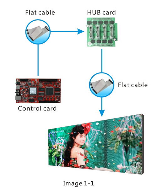
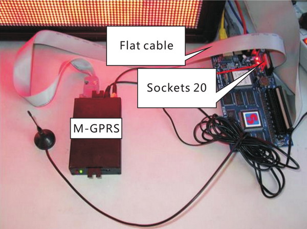
Hardware connection is illustrated with the image 1-1 below:
① Connecting control card with HUB by flat cable firmly;
② Connecting HUB J1 port with input port of LED screen by flat cable;
③ Accessing to power line and network;
④ After the control card is connected power, all the indicator lights (power, network and working )are to turn on and the working light is twinkling, which means that the control card is operating normally.
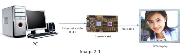
1.2 Computer and Control card connection
Connecting computer with led screen by internet cable, as follows 1-2.
2. Operating Environment and software installation
2.1 Operating Environment
Operating system: Simplified Chinese, Traditional Chinese or English WINDOWS XP,Vista.
Hardware Configuration: CPU:Pentium 600MHz or above; ROM: 512M; Graphics card: Standard VGA 256 mode or above.
Related Software: Microsoft Media Player – compulsory.
2.2 Software installation –LED set2.0 and Led editor
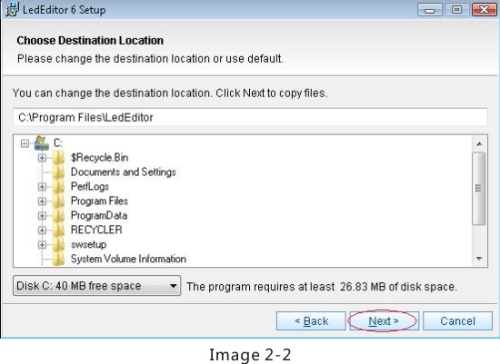
2.2.1 "LED Editor"software
Firstly put the "LED Editor" installation CD into the CD-ROM, then the Installation menu will automatically pop up, (If not, please select this CD-ROM and double-click it).Secondly, as Figure2-2 shows, select “LED Editor_Setup.exe” and operate the software installation as the installation guide.
After "LED Editor"software has been successfully installed, there will be a "LED Editor" short-cut on your desktop, and users can start the program by double click on the icon.
2.2.2 "LED set2.0"software
The software has been set before shipment by us, so no details are available here. As to he installation procedure,please refers to that of software <Led Editor>
3. Special Notes and Computer Parameter Setup
3.1 Set up computer's IP address
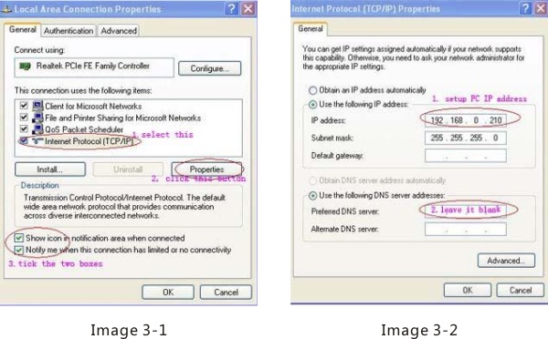
If LED Set2.0 can automatically detect the IP address, this step can be ignored. If not, manual setup is needed. Specific steps are as follows: Right click “Network Neighborhood”, choose “Properties”, open “Network Connection”, then right click “Local Connection” and choose “Properties”(see Image 3-1 below)
Please set up IP according to the notes in image 3-1, then click on"Property"button, a dialogue box will appear, as shown in image 3-2
After finishing all the settings, please click “ok” .Note the setting of IP address is subject to 192.168.0.210.
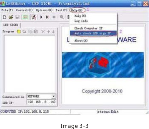
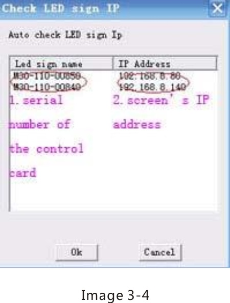
3.2 Check LED Screen IP address in <LED Editor>
Click”Help” button in the menu bar of the <<LED Editor>> software, then choose “Auto check LED sign IP” in the list to bring out a dialogue box. , as shown in Image3-3 and Image 3-4 below. And you can view the LED screen IP address in Image 3-4.
4. Simple Software Setup
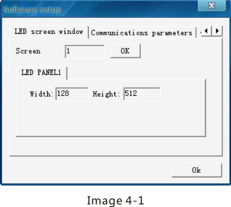
4.1 Open software setup window
Click on “Options” button in main menu, select “Software Setup” to open a new window, as shown in image 4-1. This window contains three sub-menus: LED screen window, Communication parameter and Default parameters.
4.2 LED Screen Window Setup
Screen: The number of LED screen. Input its number and then click “OK”,while the default number is 1.
Width and Height of LED PANEL: with these two parameters, users can set up the size of preview window of current project.
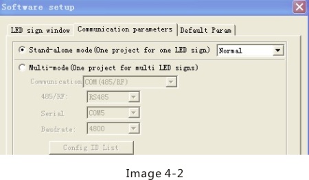
4.3 Communication parameters
There are two types of communication modes “Stand-alone mode” and “Multi-mode”, as shown in the image 4-2 below.
Stand-alone mode (Recommended): one project for one LED Screen. (Most work in this mode)
Multi-mode: One project for multi LED screens and this LED screen are with same pixels regardless of width or height.
When choose multi-mold, users need to input password.
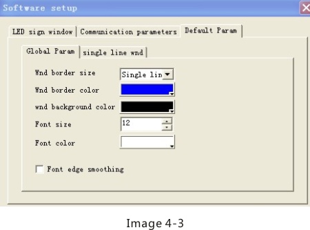
4.4 Default Parameters
Setup basic parameters for programs, it also the default parameters when open various windows, as shown in image 4-3 in below:
5. Basic Failure Resolution
● Problem: Why a line text is not centered using text window?
Solution: Make program using single line text window.
● Problem: Why two lines of 16 pixels font could not display in LED screen of 32 pixels height?
Solution: Make program using static text window. Note: If it has frame, actual height of the window is 32 minus 2 times of the frame.
● Problem: Why the size of program window could not change by moving mouse?
Solution: Check if the window is locked. Unlock the window. Change size by moving mouse or inputting values (width and height).
● Problem: Why program preview effects are slightly inconsistent with program?
Solution: LED screen playing effects should be taken as valid and binding. For example, timing part of schedule program preview isnt included.
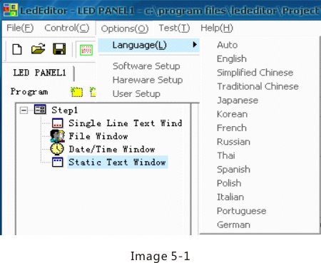
● Problem: How to revise LED Editor Language?
Solution: LED Editor Software can identify according to OS of PC automatically. This software supports three kinds of languages: Simplified Chinese, Traditional Chinese and English.(Image5-1)
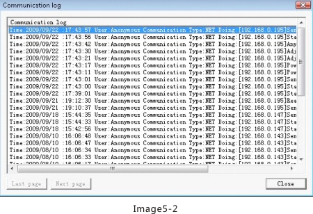
● Problem: How to view communication log about sending program and operating LED screen?
Solution: Click "Help"button on menu, select "LOG INFO"(Image 5-2)
● Problem: How to check LED screen IP address automatically?
Solution: Click "Help" button on menu, select "Auto check LED screen IP"(Image 5-3).
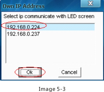
● Problem: How to select network card connecting LED screen, if there are multiple network cards in PC?
Solution: Click on"Help"menu and then select"Check Computer IP"to open the “Own IP address” window, then select in the list under IP communicate with LED screen, and click “Ok”.
● Problem: How to delete background picture?
Solution: Delete all the characters in the edit box of background file path ,and the picture will be removed.
● Problem: What’s the shortcut to adjust the position and size of the program window?
Solution: User can right click directly the mouse and choose the options like “Position” and “Size” to make adjustment, as shown in image 5-4.
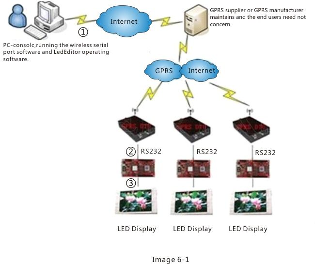
6. Special Wireless Solution
6.1 Wireless GPRS Solution
6.1.1 System connection
① Connect PC with ADSL router by cable, inserting ADSL router into Internet by telephone line or in other ways.
② Connect control card with GPRS modules by serial port 232.
③ Connect control card with display screen by HUB and flat cables.
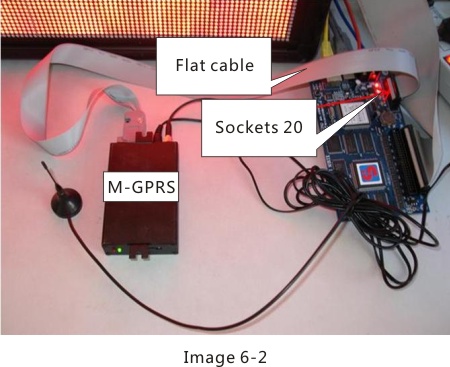
6.1.2 Hardware connection
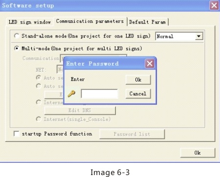
6.1.3 Setup Software
Steps for setting up LED editor:
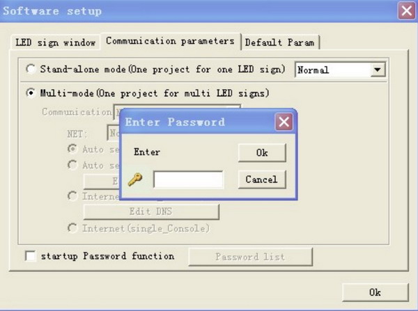
Menu bar-Options-Software setup Communication parameters, please select multi-mode then input password (default: 888), as shown in image 6-3 in below:
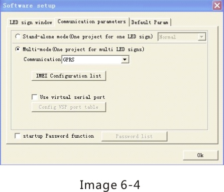
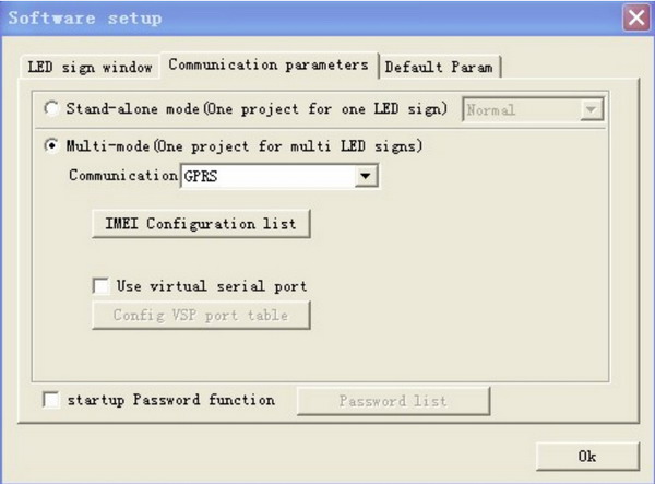
Then select IMEI configuration under GPRS mode, as shown in image 6-4 in below:
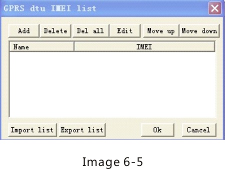
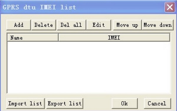
Click on “IMEI configuration list” then a dialogue box will appear, as shown in image 6-5 in below:
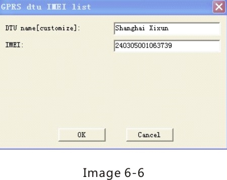
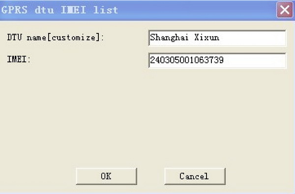
Click on “Add” button and add new terminal users, as shown in image 6-6 in below:
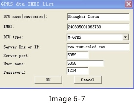
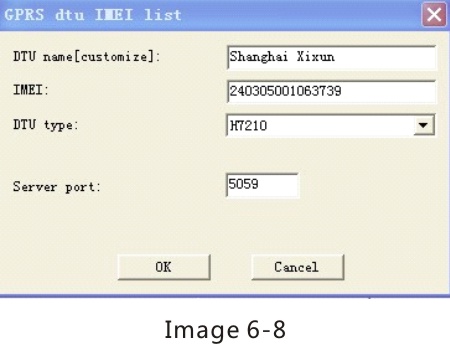
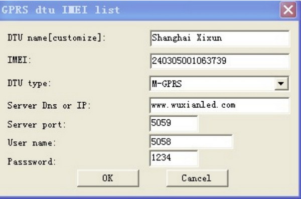
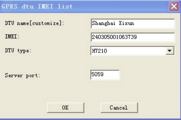
NOTE: press F5 on this interface then detailed information about GPRS terminal will appear, moreover, there is another GPRS mode: H7210 in drop down list of DTU type for users, ,and users can choose one of them according to needs. as shown in image 6-7and 6-8 in below:
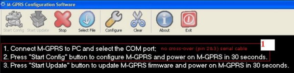
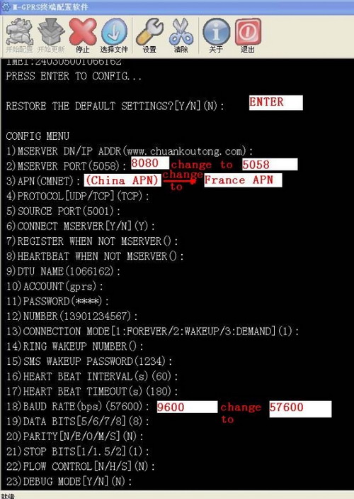
● Interface of M-GPRS (Do not change to other content)
● Interface of H7210
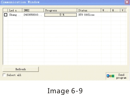
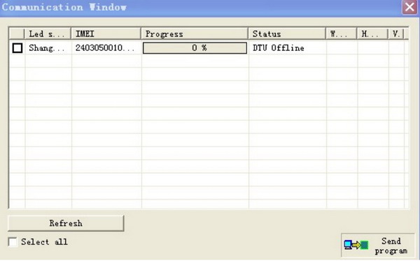
Click on “OK” button after configuring. Then click “Send program” button, as shown in image 6-9 below:
NOTE: The basic setup for domestic users has been finished, while for the abroad users, some parameters should be revised. Please refer to materials about revise and configuration of M-GPRS DTU in XIXIN LedEditor 9.0GPRS Solution for more details.
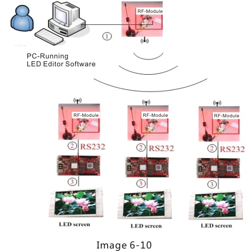
6.2 RF Solution
6.2.1 System connection:
① Connecting users' PC with RF modules by serial port line 232.
② Connecting control card with RF modules by serial port line 232.
③ Connecting control card with display screen by HUB and flat cables.
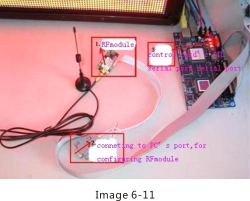
6.2.2 Connecting RF modules with control card (Factory default configuration about them has been completed, so connect them directly is ok).
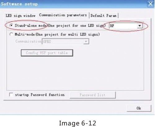
6.2.3 One PC controls one control card connecting with RF module
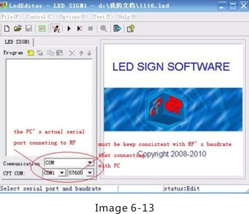
Configuration steps of LED Editor are as follows: Click “Options” on menu bar, then select“Software Setup” –“Communication parameters”-“Stand-alone mode” , “RF” at its back box. As shown in image 6-12.
After this,users can connect RF with screen as the wired one,as shown in image 6-13 below.
6.2.4 One PC controls multiple control cards connecting with RF modules
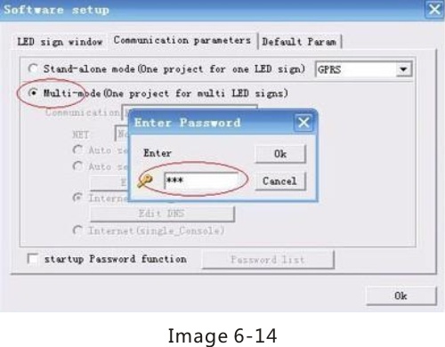
Configuration steps of Led Editor is as follows: click “Options” on menu bar, and then select “Software Setup”-“Communication parameters”-“multi-mode” , input the password<888>.As shown in image 6-14 below.
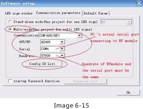
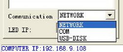
Communication: COM (485/RF) then setup relative values and ID list:
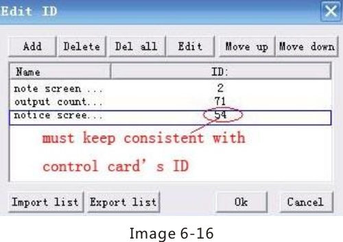
Setup ID list as shown in image 6-16 in below:
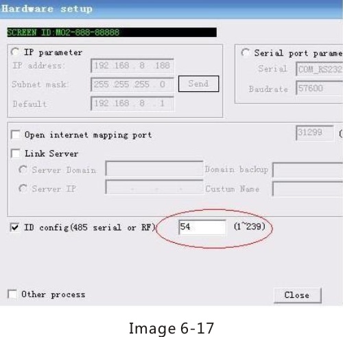
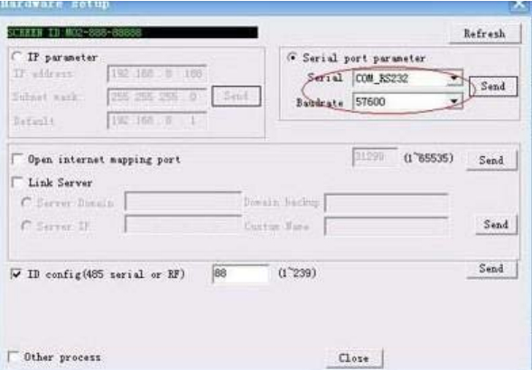
Users can search LED control card ID by the following steps: “Options” on the menu bar –“Hardware Setup”, the ID confi, as shown in the image 6-17 below.
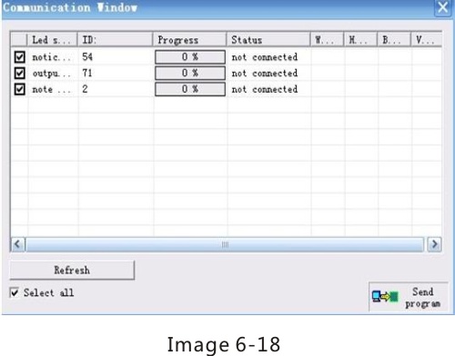
Screenshot of sending program by RF under multi-mode condition, as shown in image 6-18 in below:
6.3 Wireless 3G Communication Solution
6.3.1 System connection:
System structure is as shown in image 6-19 below.
Communication theory introduction: LED control card will auto connect to the Led Editor service center running in remote PC-console through domain name parameter so as to building up a communication link.
6.3.2 For example: PC in place B controls the screen in place A
Preparations: apply for a domain name (such as: alahover.gicp.net) from
http://www.oray.com or other dynamic DSN web sites.
Place A: LED screen; ④a Xixun Company's M-series control card; ③3G router, a 3G network card of Unicom WCDMS or Telecom EVDO.
Note: connecting 3G router with LED intelligent control card directly by cables, the two must be in same segment.
Place B: ①one PC; ②the 3G router connecting with internet.
Steps of building up a communication link, five steps are needed:
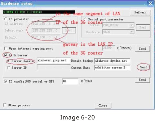
Step 1: Configure relative hardware parameters of ④LED control card in one PC installing Led Editor Software in Place A. Configuring PC server's IP address for the control card then running Led Editor Software, click "Options" on menu Hardware Setupinput password 888, as shown in image 6-20 in below:
Note:
a. Users can apply for two domain names, a main one (such as alahover.gicp.net) and a spare one (such as alahover.dyndns.org). It is recommended that these two names belong to different domain name suppliers.
b. Screen mnemonic name helps users to remember and distinguish the screen which is controlled by the control card.
c. If the PC gets static IP then please select “Server IP” option and input the IP address directly.
After finishing above steps, please confirm that control card has connected with the router by cables.
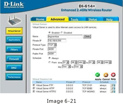
Step 2: Set up forwarding rule in Router ② configuration in place B
Inputting router's LAN IP (such as 192.168.8.1) in ①PC explorer then login. Sending data of port 31297 to ①PC IP(such as 192.168.8.225), as shown in image 6-21 below:
Note: This server port is 31297, a fixed value.
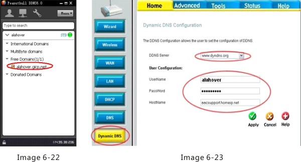
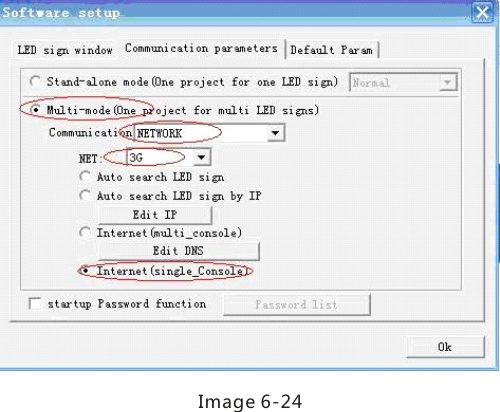
Step 3: Login the DN in place A (two methods, users can choose any one).
Method 1: download Client Software in the ①PC then login the domain names (including main and spare DN), as shown in image 6-22 in below; Method 2: Users can set up DN login in the ②router with DSN function. As shown in image 6-23 in below.
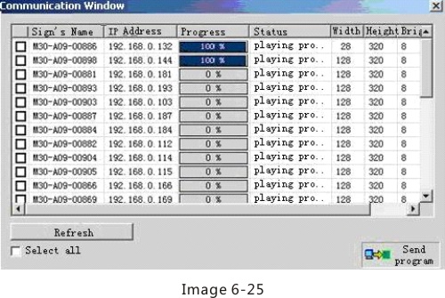
Step 4: click "Options"onmenuSoftware Setup Communication parameters select "multi-mode" and input password 888, then tick box in the front of "Internet Single-Console", as shown in image 6-24 in below:
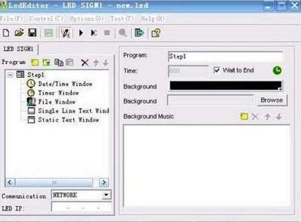
Step 5: Configuration work completed. Led Editor Software in PC could search control card client-side automatically and run instructions, such as send program and turn on/off, adjust time and brightness, etc. As shown in image 6-25 in below:
6.3.3 One PC controls multiple LED screens
Under this condition, setup steps of each control card are the same with those of one PC controls one LED screen. Topological diagram as shown in image 6-26 in below:
- See more at: http://www.fortune-display.cn/index.php/index/product/id/93.html